|
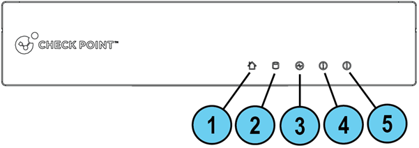
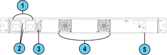
3900 Appliances Hardware Front Panel
Legend Item Component Description 1
Location LED
Off - Location beacon is turned off.
Blinking blue:
Location beacon is turned on in or with the Location button on the rear panel.
During Zero Touch configuration. 2
Storage device activity
Off - No storage device activity.
On (Green) - Read/Write activity. 3
Power supply status
Off - No power / no status.
Amber - Power supply fault was detected.
Green - All power supplies are functioning. 4
Alert
Off - No faults were detected.
Blinking red - System fault was detected. 5
System power
Off - System power is off.
On (Green) - System power is on.
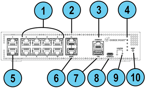
Legend Item Component Description 1 8 x 1 GbE RJ45 ports In the OS on the appliance, these interfaces are assigned the names from eth3 to eth10.
Important:
These are Pseudo Switch Ports. See .
For Zero Touch, you use port #3 (eth3).
The top row of ports (from left to right): eth3, eth4, eth5, and eth6
The bottom row of ports (from left to right): eth7, eth8, eth9, and eth10 2 1 x 10 GbE RJ45 port In the Gaia OS on the appliance, this interface is assigned the name eth11. 3 Console RJ45 port For a serial connection to the appliance. See . 4 System LEDs
Power supply status
Off - No power / no status.
Amber - Power supply fault was detected.
Green - All power supplies are functioning.
Storage device activity
Off - No storage device activity.
On (Green) - Read/Write activity.
Alert
Off - No faults were detected.
Blinking red - System fault was detected.
System power
Off - System power is off.
On (Green) - System power is on. 5 2 x 2.5 GbE RJ45 ports In the Gaia OS on the appliance, these interfaces are assigned the names eth1 (top) and eth2 (bottom).
Important - These are Pseudo Switch Ports. See . 6 Management 10 GbE RJ45 port For a connection to a remote management computer. In the Gaia OS on the appliance, this interface is assigned the name Mgmt. 7 USB port USB 3.0 port. 8 Console port USB Type-C console port for a serial connection to the appliance. 9 Location LED and button
Location
Off - Location beacon is turned off.
Blinking blue:
Location beacon is turned on in Gaia Portal or with the Location button.
During Zero Touch configuration. 10 Reset Insert a pin for 5 to 8 seconds to perform a hardware reset.
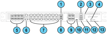
Legend Item Component Description 1 Synchronization 1 GbE RJ45 port In a configuration, use this port for synchronization with other cluster members. In the Gaia OS on the appliance, this interface is assigned the name Sync. 2 Console RJ45 port For a serial connection to the appliance. See . 3 System LEDs
Power supply status
Off - No power / no status.
Amber - Power supply fault was detected.
Green - All power supplies are functioning.
Storage device activity
Off - No storage device activity.
On (Green) - Read/Write activity.
Alert
Off - No faults were detected.
Blinking red - System fault was detected.
System power
Off - System power is off.
On (Green) - System power is on. 4 Location LED and button
Location
Off - Location beacon is turned off.
Blinking blue:
Location beacon is turned on in Gaia Portal or with the Location button.
During Zero Touch configuration. 5 8 x 1 GbE SFP ports In the Gaia OS on the appliance, these interfaces are assigned the names from eth1 to eth8.
Important - These are Pseudo Switch Ports. See .
The top row of ports (from left to right): eth1, eth2, eth3, and eth4
The bottom row of ports (from left to right): eth5, eth6, eth7, and eth8 6 2 x 2.5 GbE RJ45 ports In the Gaia OS on the appliance, these interfaces are assigned the names from eth9 and eth10.
Important - These are Pseudo Switch Ports. See .
The top port: eth9
The bottom port: eth10 7 16 x 1 GbE RJ45 ports In the Gaia OS on the appliance, these interfaces are assigned the names from eth11 to eth26.
Important - These are Pseudo Switch Ports. See .
The top row of ports (from left to right): eth11, eth12, eth13, eth14, eth19, eth20, eth21, and eth22
The bottom row of ports (from left to right): eth15, eth16, eth17, eth18, eth23, eth24, eth25, and eth26
Important - For Zero Touch, you must use port #11 (eth11). 8 Management 1 GbE RJ45 port For a connection to a remote management computer. In the Gaia OS on the appliance, this interface is assigned the name Mgmt. 9 4 x 10 GbE SFP+ ports In the Gaia OS on the appliance, these interfaces are assigned the names from eth27 to eth30.
Important - These are Pseudo Switch Ports. See .
The top row of ports (from left to right): eth27 and eth28
The bottom row of ports (from left to right): eth29 and eth30 10 Console port USB Type-C console port for a serial connection to the appliance. 11 USB ports Two USB 3.0 ports. 12 Reset Insert a pin for 5 to 8 seconds to perform a hardware reset. 13 Service tag A slide-out card that identifies the appliance and shows its serial number and MAC address. It also contains a QR code that you can scan to view documentation and on-board the appliance. Rear Panel
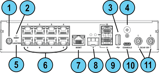
Legend Item Component Description 1 Power button Push to turn the appliance on or off. 2 Reset Insert a pin for 5 to 8 seconds to perform a hardware reset. 3 USB port USB 3.0 port. 4 Grounding screw To connect the appliance to the ground. 5 Location Insert a pin to turn on or turn off the Location LED on the front panel. 6 8 x 1 GbE RJ45 ports In the Gaia OS on the appliance, these interfaces are assigned the names eth1 to eth8.
Important:
These are Pseudo Switch Ports. See .
For Zero Touch, you must use port #1 (eth1).
The top row of ports (from left to right):eth1, eth2, eth3, and eth4
The bottom row of ports (from left to right): eth5, eth6, eth7, and eth8 7 Management 1 GbE RJ45 port For an Ethernet connection to a remote management computer. In the Gaia OS on the appliance, this interface is assigned the name Mgmt. 8 1 GbE SFP port In the Gaia OS on the appliance, this interface is assigned the name eth9 9 2 x 10 GbE SFP+ ports In the Gaia OS on the appliance, these interfaces are assigned the names eth10 and eth11.
The top port: eth10
The bottom port: eth11 10 Console port USB Type-C console port for a serial connection to the appliance. 11 Power adapter sockets Plug the power adapter cables here.
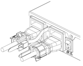
Legend Item Component Description 1 Power adapter sockets Plug the power adapter cables here. The sockets are numbered from left to right - 1 and 2. 2 Fixed cooling fan 3 Main power switch When the appliance is turned off, turns the appliance on. When the appliance is turned on, pressing and releasing the switch will start an orderly shutdown process. Alternatively, holding the switch for 4 seconds will force a machine shut down. 4 Grounding screw To connect the appliance to the ground.
Legend Item Component Description 1 Power inlet Connect the power cables to an electric outlet. The inlets are numbered from left to right - 1 and 2. 2 Restraint strip slot You can use cable restraints to avoid accidental removal of the power cables. 3 Main power switch When the appliance is turned off, turns the appliance on. When the appliance is turned on, pressing and releasing the switch will start an orderly shutdown process. Alternatively, holding the switch for 4 seconds will force a machine shut down. 4 Fixed cooling fans Numbered from left to right - 1 and 2. 5 Metal grounding plate Used to connect the grounding lug. Front and Rear Panel Port LEDs For information on the front and rear panel port LEDs, see sk183375. Grounding the 3920 and 3950 Appliances
Prepare the required grounding wire that complies with the local regulations. The minimum wire gauge is 18 AWG. One end of this grounding wire must connect to the ground in your environment. To the other end of this grounding, attach the applicable lug that matches the grounding screw on the appliance.
Place the ground lug attached to the ground cable over the protective grounding terminal.
Secure the grounding lug to the protective grounding terminal with a washer and screw.
Make sure the grounding wire does not touch or block access to other components. Grounding the 3970 / 3980 Appliance
Before you start, make sure you have these items:
A UL listed two-hole grounding lug, similar to Panduit LCD10-14A-L.
Copper grounding wire 18 AWG (the insulation color must be green and yellow to meet the IEC/UL 62368-1 CL5.6.2.2 requirement or the insulation color must comply with your local electrical regulations).
Grounding design that complies with the country or local electrical codes.
A wire crimping tool suitable for the grounding lug type.
A screwdriver suitable for the grounding screws. Prerequisites:
Insert the grounding wire in the lug (connector).
Use the crimping tool to crimp the lug onto the grounding wire.
Place the screwdriver near the appliance rear panel. Procedure:
On the appliance rear panel, locate the metal grounding plate (on the far right).
Remove two screws from the metal grounding plate (depends on which direction you want to attach the grounding lug, vertically or horizontally).
Attach the grounding lug to the grounding plate.
Make sure the two holes in the grounding lug are aligned with the corresponding holes in the grounding plate.
Insert the first grounding screw through one of the holes in the grounding lug so it goes into the corresponding hole in the grounding plate.
Use a screwdriver to tighten the first screw (maximum torque of 6 kgf×cm).
Insert the second grounding screw through the second hole in the grounding lug so it goes into the corresponding hole in the grounding plate.
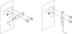
Use a screwdriver to tighten the second screw (maximum torque of 6 kgf×cm). Installing the Power Cable Restraint Strip in 3970 / 3980 Appliances
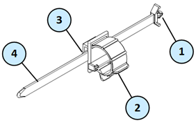
In 3970 / 3980 Appliances, the shipping carton contains two restraint strips. You can use these restraint strips to prevent accidental removal of the power cable.
Item Description 1 Restraint anchor 2 Cable loop 3 Restraint strip tab 4 Restraint strip
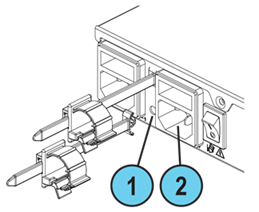
Item Description 1 Restraint strip slot 2 Power supply inlet To install the power cable restraint:
If a power cable is connected to the power supply inlet, disconnect it.
Find the restraint strip slot on top of the power supply inlet.
Make sure that the cable loop on the restraint faces the power supply inlet.
Insert the restraint strip anchor into the slot until it snaps and locks.
Connect the power cable to the power supply inlet.
Pull the restraint tab to the side to move the cable loop on the restraint strip.
Move the cable loop until you can wrap it around the power cable.
Insert the open side of the cable loop into the loop slot until it is tight against the power cable.
Make sure the cable loop is secured and the power cable cannot be removed.
Optional Hardware Components
The 3900 Appliances have optional components that you can use with the appliance:
Ear mounts for rack mounting - for 3920 and 3950 appliances
AC Power Adapter - for 3920 and 3950 appliances
Transceivers - for 3920 and 3970 / 3980 appliances For more information about installing these hardware components, see sk183199. Unless directed to do so by Check Point technical support, you are prohibited by warranty and support agreements from replacing any internal parts in the appliance. Switch Ports
The 3900 Appliances have two types of network ports:
Regular physical ports.
Switch ports. Explanation about the regular physical ports:
The regular (non-switch ports) connect to the CPU cores of the appliance directly.
For the regular ports, the output of the Expert mode command "ethtool -i <Name of Interface>" shows: driver: net_cn10k version: DPDK <x.x.x>
There are no changes in the traffic flow through the regular ports. Explanation about the switch ports: (责任编辑:) |